Christopher Schmitt MD1, Shyam Sathanandam MD1, Anthony Merlocco MD MSt FSCMR1
1LeBonheur Children’s Hospital, Memphis, TN, USA
Clinical History:
A 12-year-old female with history of 22q11 deletion syndrome and truncus arteriosus type III with interrupted aortic arch type B presented for cardiac magnetic resonance imaging (CMR). As a neonate, she underwent truncus repair using a cryopreserved aortic homograft with repair of interrupted aortic arch type B and subsequently required aortic root replacement at 6 weeks of age due to moderate to severe truncal valve regurgitation with closure of the ventricular septal defect. She also required aortic root replacement due to moderate to severe regurgitation several years later in childhood due to dilatation of the annulus and severe malcoaptation that led to the regurgitation. Immediately after her re-do aortic root replacement no abnormality could be seen in the repaired area, and in the following two months echocardiograms were limited in quality but did not demonstrate any post-operative abnormality. She then presented two years later with CMR as her only imaging. At time of CMR, she was asymptomatic and undergoing routine evaluation to evaluate pulmonary regurgitation and right ventricular volume and function.
CMR FINDINGS:
CMR (1.5T Signa HDXt, General Electric HealthCare, Chicago, Illinois, USA) showed normal right ventricular size with borderline function (RVEF 47%), and mild pulmonary regurgitation of 10%. A 25x33mm pseudoaneurysm, leftward and posterior to the aortic root with a small communication from the left ventricular outflow tract (LVOT) was incidentally found on cine steady state free precession (SSFP) imaging (Figure 1).
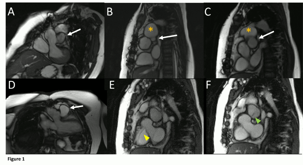
Figure 1. Demonstration of pseudoaneurysm suspected to arise from LVOT. A) Oblique LVOT view with large pseudoaneurysm appearing contiguous with LV cavity lateral and posterior to aortic valve (white arrow), B-C) Short axis views of aortic valve demonstrating pseudoaneurysm (arrow) near main pulmonary artery (yellow asterisk) with partial volume effects causing contiguous appearance, D) LVOT view of pseudoaneurysm arising from narrow neck, E-F) Short axis views in systole (E) with residual ventricular septal defect jet (yellow arrowhead), and diastole (F) with flow jet directed from LVOT into pseudoaneurysm (green arrowhead).
First phase MRA showed contrast throughout the right ventricular outflow tract, without uptake in the area of the pseudoaneurysm, with second phase demonstrating increased signal, confirming the pseudoaneurysm arose from the LVOT (Figure 2) and was not associated with a residual ventricular septal defect (VSD).

Figure 2. Contrast-enhanced MR angiogram demonstrating A) First-phase enhancement of right ventricle and main pulmonary artery (red arrowhead) with lack of contrast in the area of the pseudoaneurysm (white arrow). The right ventricular outflow tract is not seen in this plane. Panel B) demonstrates second-phase enhancement of the aorta (asterisk), pulmonary artery (red arrowhead), and pseudoaneurysm (white arrow) with slow pass-through of contrast evidenced by increased signal compared to aorta.
Cine SSFP images of the pseudoaneurysm seen in Figure 1 highlight that the large pseudoaneurysm appears contiguous with left ventricular cavity, lateral and posterior to aortic valve (panel A, white arrow). In the short axis views it was unclear if this was contiguous because of partial volume effects where the pseudoaneurysm abuts the main pulmonary artery at the aortic valve. The LVOT view of pseudoaneurysm, however, clarifies that it arises from a narrow neck connected to the LV. Interestingly, short axis views in systole and diastole (Movie 1) also demonstrate both the residual VSD jet (systole, yellow arrowhead), and a flow jet directed from LVOT into pseudoaneurysm (diastole, green arrowhead), confirming this was completely distinct.
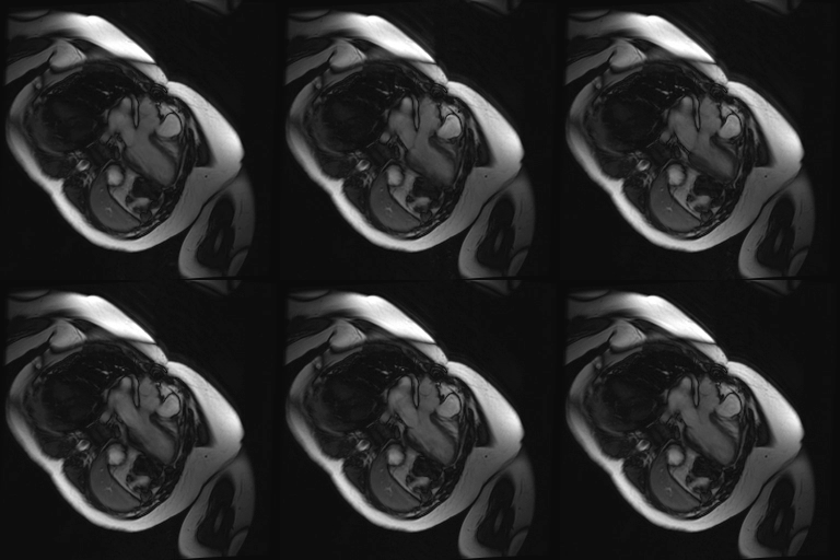
Movie 1.VSD and pseudoaneurysm – Cine sequence demonstrating intermittent shunting variably into pseudoaneurysm (during systole) and into right ventricle through VSD (during diastole) from LV outflow tract. VSD shunting is not seen throughout cardiac cycle due to through-plane motion.
Contrast-enhanced MR angiogram (Figure 2; Movie 2) further elucidated the connection when comparing first-phase enhancement to the second-phase angiography. In the first phase, the right ventricle and main pulmonary artery demonstrate lack of contrast in the area of the pseudoaneurysm, while the second-phase reveals enhancement of the aorta and pseudoaneurysm and slow flow out of the pseudoaneurysm is evident by increased signal compared to aorta.
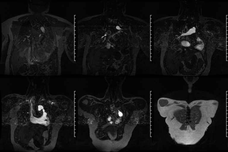

Movie 2. MRA stack of first phase (top) and second phase (bottom) demonstrates contrast present in the LV outflow tract, aorta, and in the pseudoaneurysm, which is hyperintense in second phase compared to the aorta, indicating slow drainage from the pseudoaneurysm.
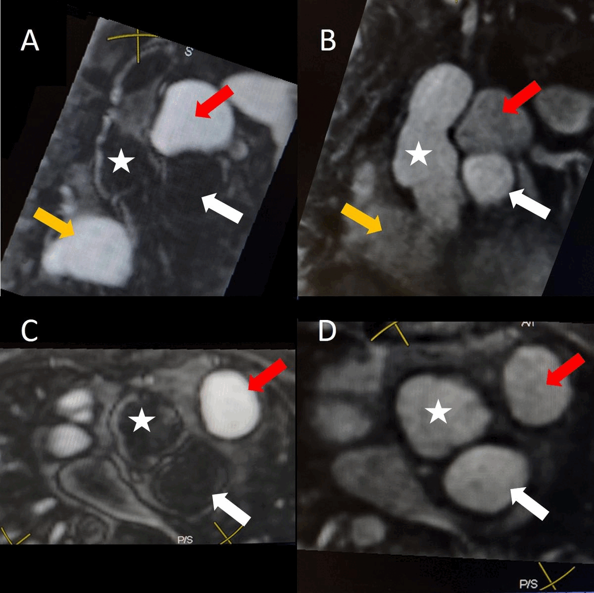
Figure 3. Oblique views from contrast-enhanced MR angiogram comparing first and second phase. In a left anterior oblique view, A) First-phase enhancement of right ventricle (orange arrow) and main pulmonary artery (red arrow) with lack of contrast in the area of the aorta (star) and pseudoaneurysm (white arrow). The right ventricular outflow track is not seen in this plane and B) demonstrates second-phase enhancement in this plane, where similar enhancement is noted in the aorta and pseudoaneurysm whereas the pulmonary artery is less enhanced. Panels C and D demonstrate a short-axis view of the same anatomy in first and second-pass respectively with arrows as described above.
Conclusion:
We discussed the case at our combined cardiology and surgical conference and after review of the imaging it was decided to schedule catheterization to obtain a transesophageal echocardiogram (TEE) and angiogram to assess whether closure can be addressed safely with more specific views of the relation to the aortic valve and the coronaries, with surgical repair to be organized if not. She next underwent catheterization with transesophageal echocardiogram (TEE). The neck of the pseudoaneurysm was small and difficult to access, although TEE assisted entry through the 3mm opening of the pseudoaneurysm. Closure strategies were compared and coils were avoided due to potential artifact on future CMR studies.
TEE images demonstrate the catheter, coursing from LVOT through the communication into the pseudoaneurysm, just proximal to aortic valve (Figure 4).

Figure 4. Transesophageal echocardiographic (TEE) images during catheterization show catheter (orange arrowhead) crossing from under aortic valve (white arrow) into pseudoaneurysm (Panel A). A 5-2 Amplatzer Piccolo Occluder (red arrowhead) was then placed at the communication between the LV and pseudoaneurysm (Panel B). Device placement confirms flow stoppage (white arrowhead) and clot formation beginning in real time (Panel C). During TEE clot formation progressed to fill the pseudoaneurysm (Panel D).
A 5-2 Amplatzer Piccolo Occluder (Abbott Laboratories, Abbott Park, Illinois, USA) was then placed at the communication between the LVOT and pseudoaneurysm (Movie 3) and no residual flow can be seen through the communication and there is evidence of clot formation (Movie 4) beginning in real time, evidenced as the contents swirled and became hyperechoic.
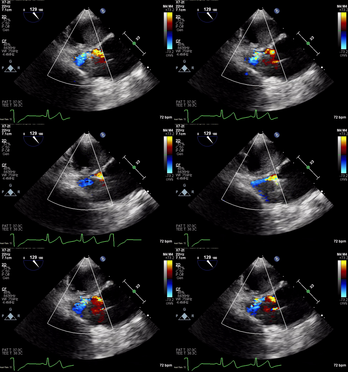
Movie 3. Transesophageal echocardiogram demonstrating Amplatzer Piccolo Occluder device seated between the left ventricular outflow tract and the pseudoaneurysm with occlusion of pseudoaneurysm flow.
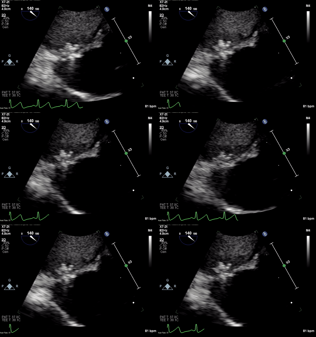
Movie 4. Transesophageal echocardiogram demonstrating Amplatzer Piccolo Occluder placement with no residual pseudoaneurysm flow and evidence of clot formation.
Rapidly the clot formation progresses in the pseudoaneurysm with no communication with the LVOT (Movie 5).

Movie 5. Transesophageal echocardiogram demonstrating clot propagation and no residual flow into pseudoaneurysm.
Angiograms (Movie 6 and 7) depict the device closure of pseudoaneurysm.


Movie 6. Invasive aortic angiography with catheter injection into pseudoaneurysm.
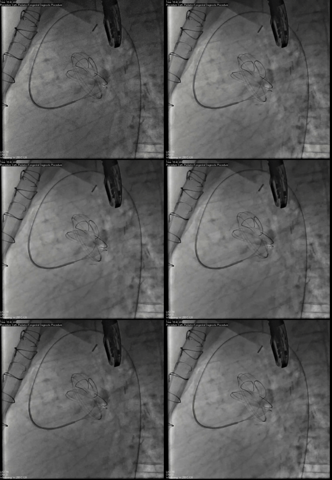
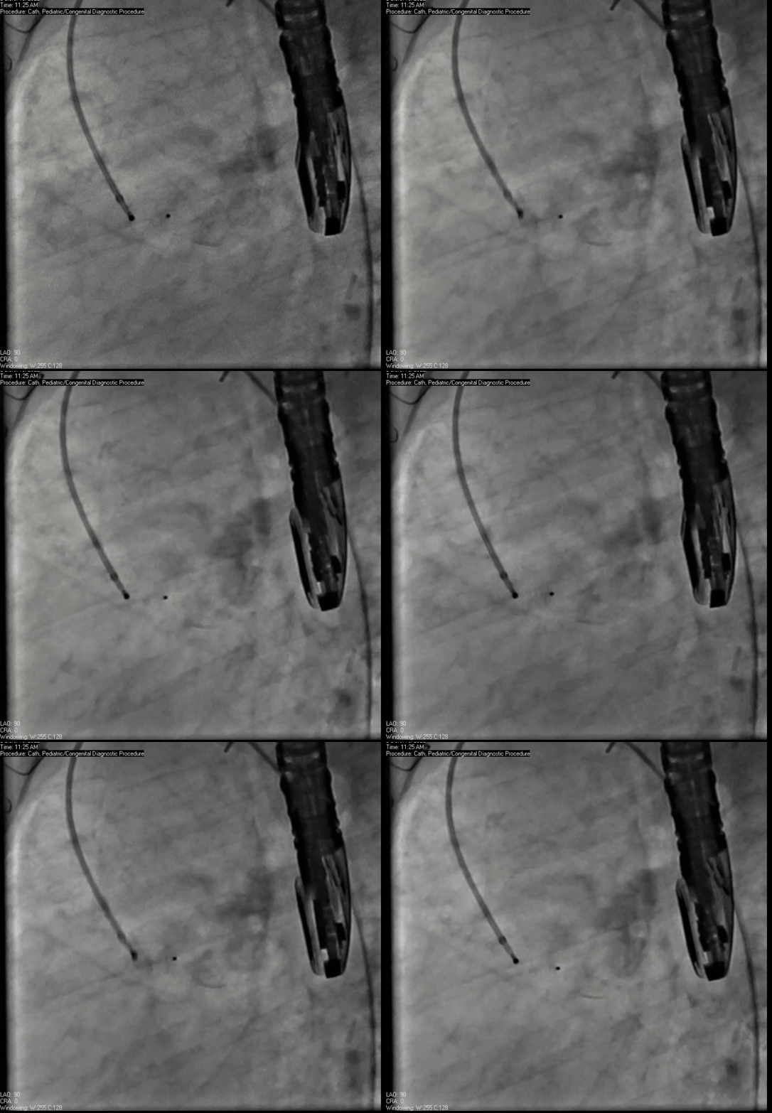
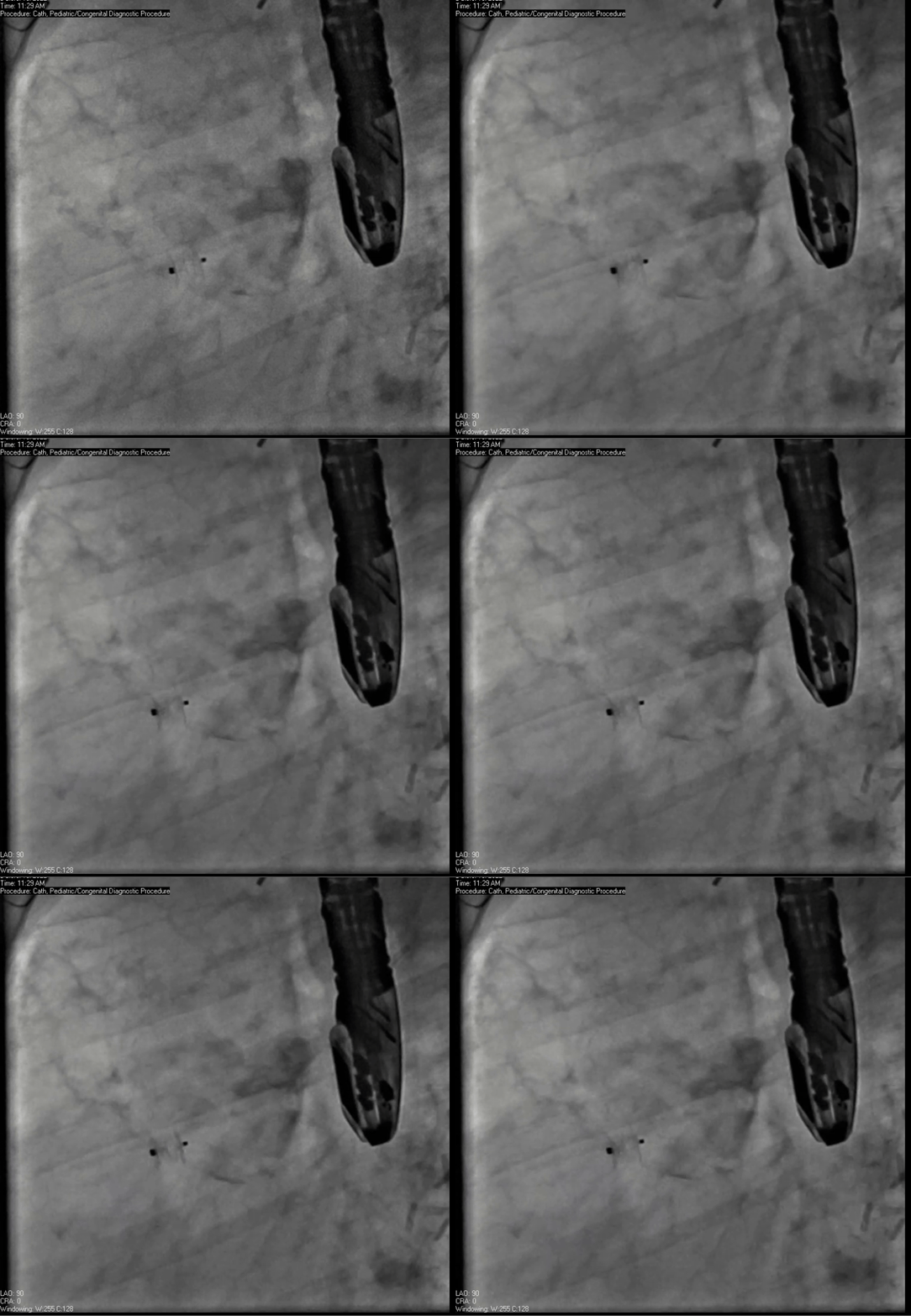
Movie 7. Invasive aortic angiography demonstrating catheter wire coil in pseudoaneurysm (left panel), release of closure device into pseudoaneurysm (middle panel), and closure device seated in pseudoaneurysm (right panel).
She was prescribed clopidogrel and aspirin upon discharge but noted non-adherence in follow-up to both medications. Clinically, she was feeling well and her echocardiogram demonstrated no residual pseudoaneurysm though this had not been seen by echocardiography previously for comparison, and her aortic valve demonstrated no stenosis and mild insufficiency.
Perspective:
Cardiac pseudoaneurysms can occur after myocardial infarction, cardiac surgery, chest trauma or endocarditis. They occur when a rupture of the myocardium becomes contained by pericardial adhesions or the epicardial wall.[1,2] Intervention is recommended because of the propensity for serious sequelae such as rupture, infection, and recurrence.[2,3] Pseudoaneurysms most commonly occur after either aortic valvular surgery or endocarditis.[4] Post-operative hyperkinesis causing abnormal pressures, inherent weakness of the aortic root, or weakness induced at surgery (tight sutures, closely placed sutures) are all proposed mechanisms for LVOT pseudoaneurysms.[2] Patients may present with non-specific symptoms though lesions are found incidentally in almost half of patients.[2] They can also present with anginal chest pain, congestive heart failure, syncope, arrhythmia, or embolism. If ruptured, patients may present with shock or sudden death.[4]
Initial evaluation with transthoracic echocardiography may show the pseudoaneurysm, but TEE, MRI, CT, and angiography demonstrate higher diagnostic yield.[2,4] Treatment is often surgical, however coils or VSD occluders have been reported5.This case demonstrates the importance of CMR imaging and surveillance imaging after congenital cardiac surgery, particularly because transthoracic imaging failed to reliably demonstrate the presence of a pseudoaneurysm. The integration of multiple imaging modalities also supported shared communication and decision making particularly in deferring the use of coils to preserve future MRI image quality. The use of TEE to guide catheter-based interventions also allowed us to evaluate the effectiveness of closure with demonstration of clot formation in real time.
Click here to view the entire case on CloudCMR
References:
- Yeo TC, Malouf JF, Oh JK, Seward JB. Clinical profile and outcome in 52 patients with cardiac pseudoaneurysm. Ann Intern Med. 1998 Feb 15;128(4):299-305.
- Chen F, Wei S, Xiong L, Liu F. Post-traumatic left ventricular outflow tract pseudoaneurysm. Ann Thorac Surg. 2014 Jan;97(1):311-2.
- Enseleit F, Grünenfelder J, Braun J, Matthews F, Jenni R, van der Loo B. Formation of pseudoaneurysm after aortic valve replacement without previous endocarditis: a case-control study. J Am Soc Echocardiogr. 2010 Jul;23(7):741-6.
- Hulten EA, Blankstein R. Pseudoaneurysms of the heart. Circulation. 2012 Apr 17;125(15):1920-5.
- Romaguera R, Slack MC, Waksman R, Ben-Dor I, Satler LF, Kent KM, Goldstein S, Wang Z, Corso P, Bernardo N, Suddath WO, Pichard AD. IMAGE CARDIO MED: Percutaneous closure of a left ventricular outflow tract pseudoaneurysm causing extrinsic left coronary artery compression by transseptal approach. Circulation. 2010 Feb 2;121(4):e20-2.
Case prepared by:
Eddie Hulten, MD, MPH, FACC, FACP, FSCMR, FSCCT, FASNC
Lifespan Cardiovascular Institute, Rhode Island, the Miriam and Newport Hospitals
Warren Alpert Medical School, Brown University
Uniformed Services University, Bethesda, MD
Editor-in-Chief
Sylvia S.M. Chen, MD


